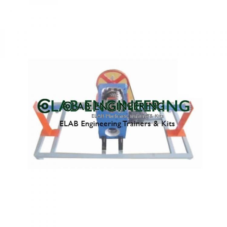
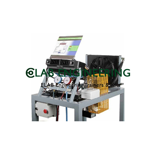
The trainer should be designed to demonstrate the theory and operating characteristics of todays modern braking systems, ABS system of various types are being included on newer vehicles as it greatly improves the control of the driver during braking, which feature computer controlled anti-locking or skid-control systems. The unit should consist of original automotive ABS braking components, which should be mounted onto an integrated floor stand, made from powder coated electro galvanized steel, that are mounted onto wheels for mobility. A color coded schematic chart, under a lexon polycarbonate protective screen, of the ABS system and circuit’s, should also be mounted onto the trainer for reference.
Specifications:Similar items like Anti-Locking Braking System Trainer you may view
ELAB Engineering is a leading manufacturer, supplier and exporter of anti-locking braking system trainer and a complete range of engineering laboratory and technical training equipment. We supply high-precision, lab-grade instruments in bulk to engineering colleges, universities, technical institutes and industries across 55+ countries — with competitive tender pricing, full export documentation and reliable after-sales support.
As a leading manufacturer, supplier and exporter, we deliver tender-grade quality with documented compliance to institutions, laboratories and training facilities across 55+ countries.
Every unit is manufactured to international quality standards and tested before dispatch, with QC documentation and calibration certificates included.
Established export channels across Africa, Asia and the Middle East, with complete shipping documentation, certificates of origin and customs paperwork.
We offer customisation for tender specifications, OEM branding, voltage variants and bulk institutional orders to match your exact requirement.
Technical consultation before purchase, installation guidance, operator training documentation and responsive after-sales support from our team.
Trusted by institutions, governments and industries worldwide for reliable, tender-documentation-ready supply.
Practical laboratory training & coursework experiments
STEM education & physics / chemistry / biology demos
Process quality, testing & calibration requirements
Clinical lab, diagnostics & pathology applications
Ministry, defence research & PSU lab infrastructure
UNICEF, WHO, UNDP & bilateral aid procurement
Skill development & technical training labs
Direct & sub-contractor tender fulfilment
ELAB Engineering is a recognised manufacturer, supplier and exporter of Anti-Locking Braking System Trainer. We supply this product across our complete export network — from individual institutional purchases to large-scale tender supply contracts.
All shipments include complete export documentation, customs paperwork & freight handling.
Request a custom quote, full technical datasheet, or place a bulk / tender enquiry. Our specialists respond within 1 business day with pricing, lead time and export documentation.
Common questions from buyers, procurement officers and technical evaluators about ordering, customisation, lead time and documentation.


.jpg)

-lab-74867268.jpg)